Activity: Fluid dynamics
It's all about flow.
In this section we will deal with the simplified case of steady flow in ideal fluids. When water flows through a pipe there is friction between the water and pipe. This slows down the water in contact with the pipe which complicates the flow.
An ideal fluid is incompressible and has zero viscosity
The water in this clip is certainly not flowing steadily, you can see that the water close to the banks is travelling slower than in the middle and there is a lot of turbulence in the fast moving sections (rapids).
The flow of fluid can be mapped out using flowlines and streamlines.
Flowlines
Lines that show the path of individual particles of fluid, here shown in an Algodoo simulation.
Streamlines
Lines that show the velocity of particles at any moment in time, again Algodoo shows this nicely.
If the flow is steady these lines will be the same and won't change with time.
If the diameter of the pipe gets smaller the lines must get closer.

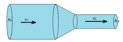
Consider the pipe shown below carrying an ideal fluid of density ρ.
Lets first look at the left side.
- How far does the fluid move in one second?
- What volume of fluid flows through the pipe per second?
- What volume passes through the right side per second?
- Explain why the fact that the fluid is ideal implies that the volume in = volume out of the pipe and show that:
A1v1 = A2v2
Fluid flows through a pipe like the one in the digram
- 3m3 of fluid flow into the pipe per second. If the radius of the first pipe is 4 m. Calculate the velocity of the fluid flowing in.
- calculate the velocity of the fluid flowing out if the second pipe has radius 1m.
Check your answers with this simulation.
Note how the streamlines get closer as the speed increases. This is used in wind tunnels to see where the air flows fastest.

In this section we will make extensive use of the PhET simulation Fluid pressure and flow which is where the animations come from.
Consider the fluid flowing in the pipe shown below:
The red dots represent particles of liquid but the pipe is full.
- Does the velocity change (think of the continuity equation)?
- As the liquid goes uphill what happens to the PE of the particles?
If the liquid is gaining energy work must be done.
Consider this more complicated situation
- Why does the velocity increase?
- What energy changes are taking place?
- Is work done on the water?
We can see that the energy increases as the water flows along the pipe so work must be done. Let us analyse the situation in more detail.
First we must realise that something must be pushing the liquid, like a pump or piston.
The animation is a bit rough but hopefully you get the point that to make the liquid flow you need to increase the pressure.
Consider this case:

Pressure from the water outside the pipe pushes on each end but the pressure at the bottom is bigger forcing the liquid through the pipe.
- Why does the liquid move further at the top end?
- If the velocity in the lower section is constant what can you deduce about the Pressure inside this section of pipe and the pressure outside?
- Write an expression for the work done on the water by the force at the bottom end.
At the top end the water moves in the opposite direction to the force, F2.
- What can you deduce about the works done at the top end?
- Show that:
Net work done, W = P1A1x1 - P2A2x2
- If V = Ax = m/ρ show that

- Write an expression for the change in KE and PE energy when the fluid flow up the hill.
- The work done will equal the gain in energy, by equating these expressions show that:

This leads to the Bernoulli equation:

Note that this only applies along a streamline.
Example:
Water flows into a pipe of radius 2 cm at a rate of 100 cm3s-1 at a pressure of 500 kPa.
- Calculate the velocity of the water.
The pipe is connected to a thicker pipe of radius 5 cm that is 4m above the height of the first one.
- Calculate the velocity in the second pipe.
- Calculate the pressure of the water in the top pipe.
Use this GeoGebra simulation to check your answers (note that the radius and height are not the same scale)
Consider a bucket with a hole in the bottom.
 Note that because the top and the bottom are open, the pressure is the same as atmospheric pressure at both openings.
- Apply Bernoulli's equation to this situation and show that if the bucket drains slowly and we can assume v1 = 0

You might have noticed the vertical tubes (manometers) on the GeoGebra simulations. These measure the pressure of fluid in the pipe, they are not to scale since they would not fit on the page if the liquid was for example water.
- Set both pipes at the same height.
- Set the first pipe to 1.6 cm and the second to 0.4 cm
- Set the flow rate to 800 cm3s-1 the density to 1000 kgm-3 and P1 to 1000 kPa
- Note the difference in height of the manometers.
- Reduce the flow rate to 400 cm3s-1 and observe the change in Δh.
This arrangement can be used to measure the flow of liquid in a pipe.
Show that the equation...

...agrees with the simulation.
This is the same idea but without the constriction
 The streamline shown ends in the tube with zero velocity. The pressure here is called the stagnation pressure.
- Apply Bernoulli's equation to the streamline from the end of the left pipe to the bend in the right pipe and show that:

This can be adapted for use with gases
 Explain what causes the difference in fluid level.
Real fluids have a sort of internal friction called viscosity. This means that the fluid in contact with the pipe has a lower velocity than the fluid in the centre. This can be shown by switching on the friction in the simulation.
The animation above is an example of laminar flow. Notice how the different layers don't mix.
Viscocity (η) ![]()
Viscosity is defined in terms of the force between two plates moving parallel to each other separated by the fluid.
The force require to move the plate is proportional to its velocity (v) the area of the plate (A) and the separation of the plates L, so:

The constant of proportionality is the viscosity:

- Show that the units for viscosity are N s m-2
For a sphere moving through a fluid such that the flow around the sphere is lamina the force opposing the motion of a sphere of radius r travelling with velocity, v can be expressed simply as:

I write the formula this way since it is easy to remember since it reads like "we are 6 pie eaters"
A short break to learn some Swedish.
Terminal velocity
A body reaches terminal velocity when the drag force equals its weight. In the simple case of a sphere moving through a viscous fluid we can use Stoke's law to model the situation.
 Consider the situation of the ball ball shown. It has density ρs and is falling at terminal velocity through a fluid of density ρf.
- Write an expression for the bouyant force Fb.
- Write an expression for the drag force Fd.
- If the forces acting on the sphere are balanced show that

If the velocity of flow in a pipe (diameter r) becomes to fast the flow becomes turbulent. This happens when:
It's strange that the IB data book uses r as diameter leading to many people (including me) to think it represents radius. I guess the examiners will be lenient here.

- Show that the the Reynolds number has no units.
Rather an old clip but some very neat demos and an idea of how important this seemingly insignificant number is.